The RM-10 was designer Roger Modjeski’s masterpiece in creating the most efficient and serviceable high end tube amplifier that one reasonably can. Notably, it is claimed to reliably output 35w per el84 pair with a 700v B+. Modjeski points out that the power usage effectiveness (think datacenter PUE) of this amp is an uncommon 70w total output for 70w idle consumption. Mine idles at 62w with bias at .2v or 7w cathode current per tube. Funny enough consumption doesn’t noticably rise above 62w when playing fairly loud music on my 96db/w/m speakers.
This amplifier has all of what I’ve come to consider (after owning.. and having to fix many, many tube amps) the required features in mature tube amplifier design:
- per-channel B+ fusing (per tube even better)
- per-channel adjustable fixed bias
- tube sockets mechanically fixed to the chassis, not to pcb
- non-unobtanium tubes
- solid state rectification (negotiable)
- easily accessible components (no pcbs buried under other pcbs that require de-soldering everything to access)

The power supply is very elegantly engineered - from the manual:
“Taking a lead from its big brother, the RM-10 power supply uses a voltage doubler to receive best regulation from the transformer. This also conveniently provides a stiff and exact half voltage for the screen grids of the EL-84 without using a complex regulator. Since it is tied to a fraction (1/2) of the main supply voltage (B+) it is always just right. I believe the RM-10 to be the first commercial amplifier to employ this technique. The EL-84 filaments are connected in series to allow a 12.6 volt winding to provide both filament power and bias voltage, thus eliminating the fragile, low current bias winding and its delicate fusing.”

This example I have here looks like it has been through a few owners. I’m fairly certain I saw this same one on usaudiomart a couple years before I bought it. Interestingly, there was an obvious cold solder joint on the negative side of the 700v doubler - causing an intermittent popping and crackling that would come and go every few days. Everything looks original inside, so I suspect its just been that way for the last 20+ years and previous owners kept thinking ’ehh this thing is just noisy’. Also questionable was the incorrect 2A B+ fuses I found in place of .2A!
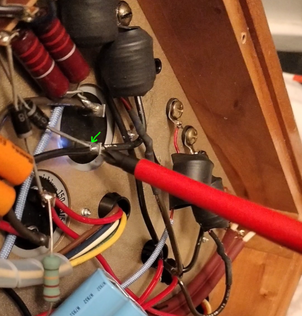
See the arc?
I won’t fault Music Reference for a cold solder joint on a hand-made amp; I’m sure they would have fixed it for me all those years ago. After that little bit of servicing, it has been silent and reliable. It runs every waking moment that I’m home - I work from home, and I fall asleep with it left on more often than not, so thats a lot of run time. Conservatively, lets say 20hrs x 5 days = 5200 hours in the last year.
Something else worth noting - i have seen a bit of copypasta online suggesting that not all of the RM-10s are 35w, even the mkIIs, or that maybe these first generation ones are 25w. I’m not sure if any of this is true, but what i do know is that serial number 1066 here definitely outputs a 35w 1khz sine wave, and comparing the underside of mine with the 6moons mkII photograph and the mkII manual, the only differences I can make out are:
- mine doesnt have the mono bridging switch
- mine specifies 140ma bias instead of 300ma
- mine has inductors on the outputs
- mine has larger 1/2w bias pots
- mine specifies 200ma cathode fuses, mkII specifies 160ma
- mkI cathode fuses have a component connecting them to the tubes, not in mkII (inductor perhaps?)
- various components are different brands
- my mkI has a larger power transformer than mkII
- mkII clearly has simple 3-wire push-pull output transformer, mine has something more complex (red B+, white to cathode fuses, green and yellow to cathodes, blue and brown to plates). feedback windings?
These changes appear to exist to reduce parts count and cost rather than anything else. There are no other significant changes to the circuit that i can see. Yes I have measured my B+ and it is indeed around 700v.
What follows are measurments taken with my Keysight scope into an 8 ohm resistive load. All measurements are at the specified .14v 41% bias point.
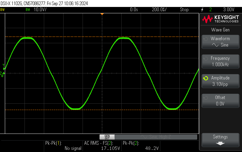
Above is evidence of the 35w claim. Power is V^2 / R, so thats 17.105^2 / 8 = 36.57w at 1khz. This is one click ‘past’ clipping on the indexed knob on my function generator, so ~34-35w is indeed clean. This is with 12w JJ el84s. 8 ohms.
This first version specifies .14v at the bias points, while MKII specifies .3v. .3v does indeed clean up the crossover distortion here. As you can see in the photos, this represents the drop accross 10ohm resistors; so .3v drop is .03 amps for the pair, or 10.5w per tube, or 88% el84 dissipation. .14v bias is 5w per tube, or 41% el84 dissipation. These numbers are all cathode current, so plate current will be a little more due to grid/screen leakage.
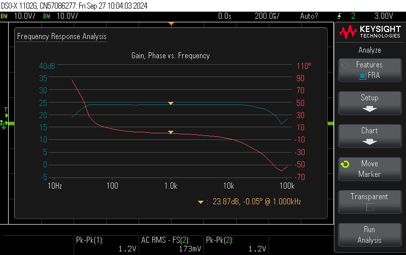
Above is the frequency response at ~35w into 8ohms. (one ‘click’ under the above clipping level)
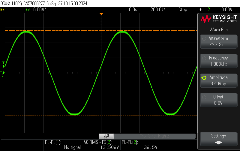
Above is output when ’light loaded’ - 4 ohm tap into 8 ohms. 22.8w. The trade-off with light loading is damping factor for efficiency. Its less obvious in this image, but this is right at clipping.
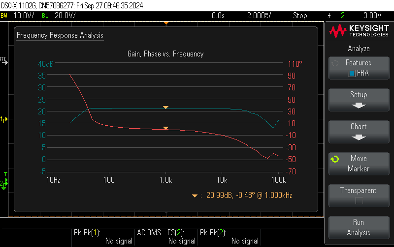
And as before, heres the response for 4 ohm tap into 8 ohms - ~22w. I believe that rolloff starts at around 50hz. Notice phase rotation is fairly consistent from ~50hz-20khz.
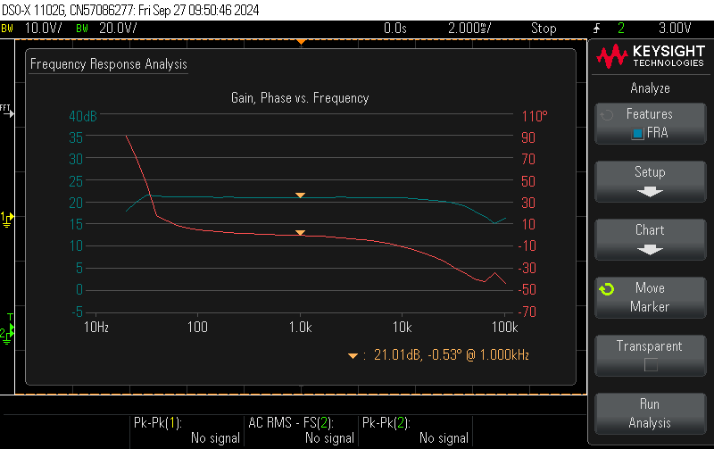
Here is the repsonse at a more relaxed 10.5w, from the 4 ohm tap, into an 8 ohm load. Notice freqeuency response of a tube amp like this is a bit wider when its not working as hard.


